Making SmartFusion2 Productive in Brownfield Systems
Introduction
SmartFusion2 is an interesting platform: an FPGA tightly coupled with a Cortex‑M3 microcontroller, security features baked into silicon, and a toolchain that reflects its long industrial heritage. It is powerful—but it can also feel heavy if your primary goal is simply to get code running, talk over UART, and start experimenting.
This post describes a software-first workflow for working with the Microcontroller Subsystem (MSS) on Microchip SmartFusion2, based on hands‑on work with the M2S090TS evaluation board. The emphasis is deliberately on getting productive quickly, especially for software and security engineers who do not want to live inside FPGA tools.
Rather than documenting every register or Libero click-path, this article focuses on the decisions, trade-offs, and minimal setup that make the platform usable and predictable in practice.
Context: An Older Platform and Brownfield Devices
SmartFusion2 is not a new platform. It has been deployed in real products for years, often in long-lived industrial, infrastructure, and security-sensitive systems. This matters, because a large part of its relevance today comes from brownfield deployments, not greenfield designs.
In engineering terms, brownfield devices are systems that:
- Are already deployed or close to deployment
- Have fixed hardware constraints
- Cannot be redesigned freely without high cost or risk
- Must be extended, maintained, or upgraded in place
This is in contrast to greenfield designs, where hardware, software, and tooling choices can be made from scratch. For brownfield devices, the problem is rarely “design the perfect system.” Instead, it is:
- How to add new functionality without changing hardware
- How to modernise software workflows on top of legacy platforms
- How to introduce new security mechanisms without destabilising a proven system
SmartFusion2 fits squarely into this category. Many teams encounter it not because they would choose it today, but because it is already part of an existing product or certification boundary.
The approach described in this article is shaped by that reality: it assumes fixed hardware, aging tooling, and long product lifetimes, and focuses on making such systems workable and productive rather than ideal.
Philosophy: Software First, Hardware Fixed
The guiding idea behind this setup is simple:
Fix the hardware early, keep it minimal, and let software move fast.
SmartFusion2 allows deep hardware customisation, but recompiling FPGA designs is slow, license-gated, and unnecessary for early development. By freezing a small, known-good MSS configuration and distributing it as a ready-to-flash image, software developers can iterate without touching Libero at all.
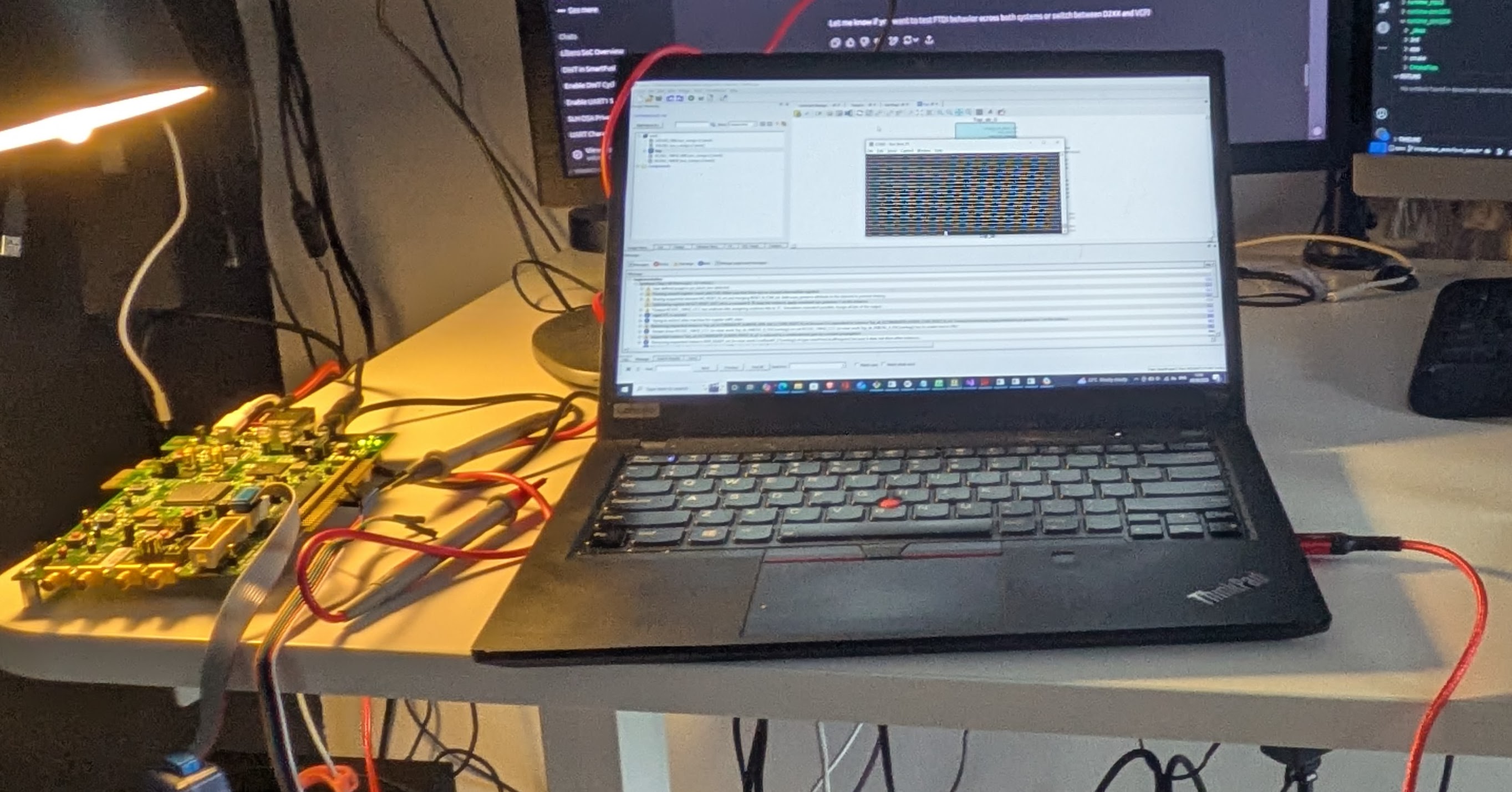
A Minimal and Repeatable Development Platform
The evaluation setup is intentionally designed to remove friction during early development. All interaction with the board is handled through a single USB connection. The kit exposes a built-in FlashPro programmer, so no external probes or adapters are required to establish a usable development environment.
In practice, the setup reduces to three fixed elements:
- One USB cable used for both programming and UART console access
- A jumper configuration that allows flashing of both the FPGA fabric and firmware
- A known, static DIP-switch configuration
Once configured, the board can remain in this state for the entire development cycle.
On the hardware side, the FPGA design is deliberately minimal. Only the components required to make the MSS usable are enabled: a Cortex-M3 clocked at 166 MHz, APB buses running at full core speed, a single UART for console output, GPIO-mapped LEDs for visible execution state, and one GPIO routed as an external trigger for measurement and debugging. There is no custom logic, no accelerators, and no unused peripherals. The result is a predictable execution environment that behaves identically on every boot.
The FPGA design is developed using Libero SoC, Microchip’s integrated FPGA design environment for SmartFusion2. Libero is used to configure the FPGA fabric, MSS peripherals, clocks, and pin assignments, and to generate the final FPGA bitstream. It is a comprehensive but heavyweight toolchain, typically operated by hardware teams, and it requires licenses, long build times, and detailed device-level knowledge. Libero produces both the FPGA bitstream and the associated firmware artifacts, which can then be used to build a BSP. Firmware engineers can subsequently continue software development in SoftConsole IDE or, for more low-level workflows, directly edit the code (e.g., in vim) and build it using a GCC-based ARM toolchain.
To keep the workflow software-centric, the FPGA can be programmed using FlashPro Express rather than a full Libero project. The hardware is delivered as a pre-built programming job, which avoids licensing requirements and lengthy synthesis or place-and-route steps. Every developer works against an identical hardware configuration, and flashing the FPGA becomes a one-time operation that takes seconds (well, maybe longer…).
The firmware follows the same philosophy. It does only what is necessary to confirm that the platform is alive: initialise clocks and GPIOs, bring up a UART console, and provide a visible heartbeat via an LED. If UART output is visible and the LED toggles, the system is ready. Anything beyond that belongs in application code, not in bring-up firmware.
Two firmware build modes are supported: a debug configuration that runs from SRAM for fast iteration, and a release configuration that runs from on-chip non-volatile memory for deployment-like testing. This split keeps development efficient without sacrificing realism.
Enabling UART
Using SmartFusion2 from Linux works well in practice, but one detail regularly trips people up: UART access via the on-board FTDI device. Microchip’s documentation is very complete for Windows, but Linux workflows are less well covered (even though Microchip support is excellent). The issue is not the hardware, but how Linux binds drivers to the FTDI interfaces by default.
The evaluation board exposes a multi-interface FT4232H USB device. From a hardware perspective, several virtual serial channels are available. From the Linux kernel’s perspective, however, only one of those interfaces is automatically bound to the ftdi_sio driver, while the remaining three are not.
The FT4232H device connected to the SmartFusion2 micro-USB port sets up four virtual ports. Under Linux, the root device is listed as:
Bus 003 Device 005: ID 1514:2008 Actel Embedded FlashPro5and each individual interface as
/:  Bus 03.Port 1: Dev 1, Class=root_hub, Driver=xhci_hcd/4p, 480M
    |__ Port 4: Dev 5, If 0, Class=Vendor Specific Class, Driver=, 480M
    |__ Port 4: Dev 5, If 1, Class=Vendor Specific Class, Driver=, 480M
    |__ Port 4: Dev 5, If 2, Class=Vendor Specific Class, Driver=ftdi_sio, 480M
    |__ Port 4: Dev 5, If 3, Class=Vendor Specific Class, Driver=, 480M
By default, Linux binds ftdi_sio only to interface If 2. In practice, the remaining interfaces can also be bound to ftdi_sio. You can force the driver to match them as follows:
echo 1514 2008 | sudo tee /sys/bus/usb-serial/drivers/ftdi_sio/new_idThis command causes the kernel to rebind the remaining FTDI interfaces, which can be verified in dmesg. After that, UART access is available via the /dev/ttyUSBx device corresponding to interface If 3 (the last FTDI interface).
(Credit goes to a colleague who helped identify this behaviour.)
Flashing Firmware from the Linux Command Line
Flashing firmware from the command line is not officially supported by the standard toolchain; Microchip recommends using SoftConsole. The GUI relies on OpenOCD (bundled with SoftConsole) and GDB, both of which connect to the on-chip debugger via USB.
A command-line workflow is essential for automation, CI, and reproducible Linux-based development. While it is possible to reverse-engineer the OpenOCD invocations used by the GUI, there is a cleaner alternative.
The programmer is supported by the pyOCD toolset, which provides a practical and well-maintained solution for flashing and debugging SmartFusion2 devices using an external probe.
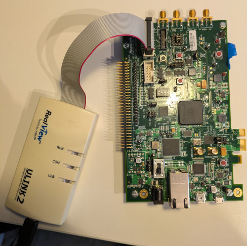
SmartFusion2 evaluation boards expose a standard RVI debug header, which allows the use of common ARM debug probes such as:
- Keil ULINK (CMSIS‑DAP)
- Other CMSIS‑DAP compliant probes
- SEGGER J‑LINK
A key drawback of using an external programmer is that jumper J8 must be moved to position 2–3 in order to program the FPGA bitstream using FlashPro 4 or 5.
pyOCD supports these probes out of the box and provides a clean, scriptable interface suitable for automation.
In practice, the workflow looks like this:
- Connect the external probe to the RVI header
- Install pyOCD on the host system
- Install the CMSIS device pack for the SmartFusion2 target
- Flash binaries directly from the command line
Once set up, flashing a firmware image becomes a single command, which integrates naturally into Makefiles, CMake builds, or CI pipelines. This avoids reliance on vendor GUIs while remaining robust and repeatable.
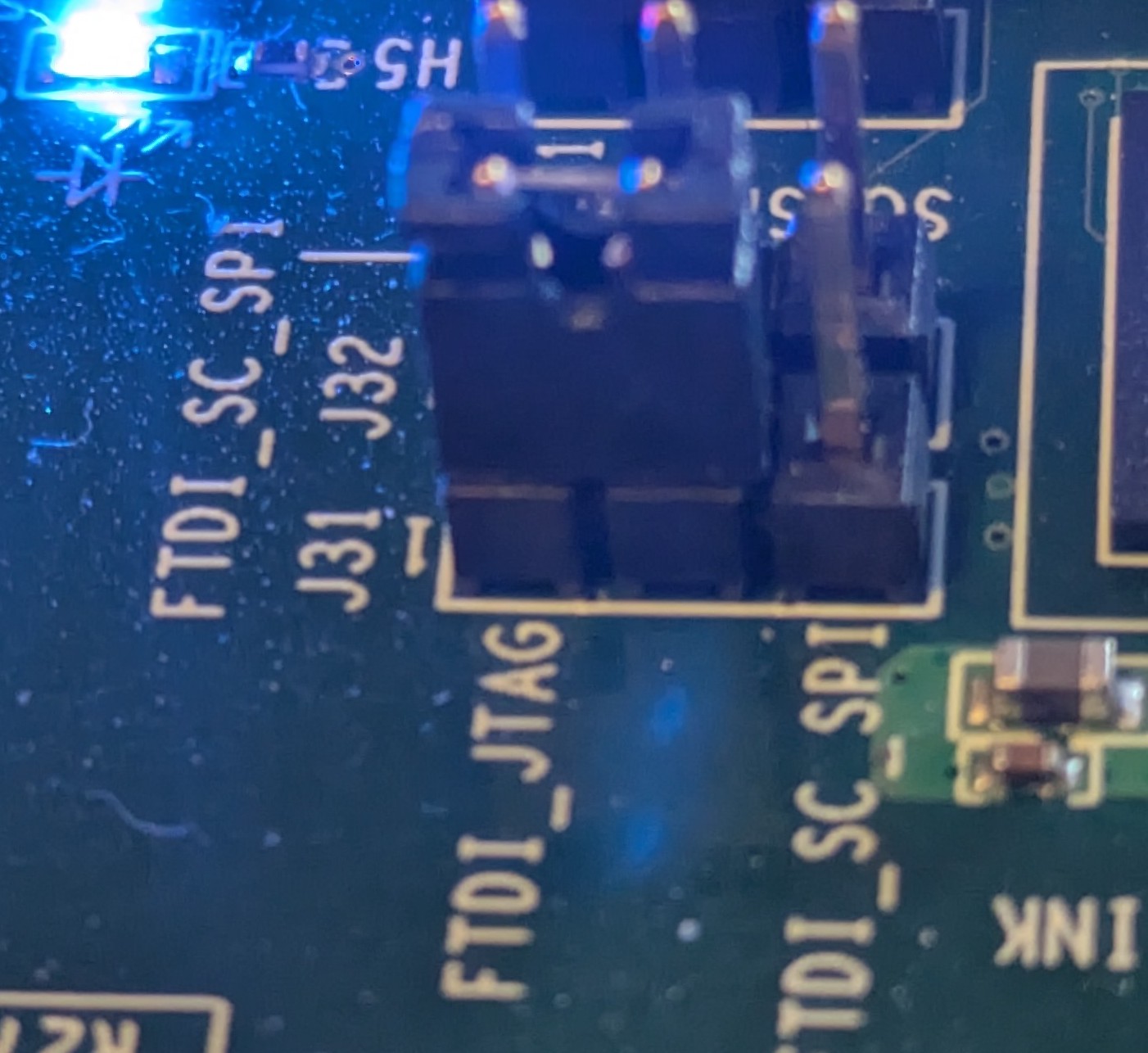
In practice, this looks as follows:
- HW configuration: The user connects ULINK2 into the RVI port, connects pins 1-2 of jumper J8 and J31 (as below).
- SW configuration: Once pyOCD is installed, the user needs to download a CMSIS package for M2S090 board. No special udev rules are required.
 pyocd pack install m2s090
Downloading packs (press Control-C to cancel):
    Microsemi.M2Sxxx.1.0.65
Downloading descriptors (001/001)

> pyocd list -p
  #   Probe/Board                           Unique ID   Target
----------------------------------------------------------------
  0   Keil Software Keil ULINK2 CMSIS-DAP   V0010M9E    n/a
With this setup, flashing becomes straightforward:
pyocd flash --target m2s090 app/hello.bin
pyocd reset --target m2s090 -m hw
The reset command resets the board, and the -m hw option ensures that the device does not enter debug mode.
For measurement and analysis, UART is often not the most convenient interface.
As an alternative, SEGGER J-LINK or CMSIS-DAP programmers can be used. The RTT interface provided by J-LINK enables fast data transfer between the device and the host, which can be useful for collecting data for constant-time analysis, serving as an alternative to UART.
In addition, the board includes a Trace Port Interface Unit (TPIU) supporting ITM and ETM (Instruction Trace Module / Embedded Trace Module), which can also be used as an alternative to RTT.
Using usbip for Remote Access
In shared lab environments, it is often useful to access SmartFusion2 boards remotely—for example, from CI servers or developer machines without physical USB access. It also helps avoid accidents, such as spilling coffee on expensive hardware.
In such cases, usbip can be used to export a USB-attached debug probe (and, if needed, the FlashPro interface) from a remote host and reattach it on the client machine over the network.
This enables:
- Remote firmware flashing using pyOCD
- Centralised lab hardware shared across multiple users
- Integration of physical boards into CI systems
Configuration is very simple: * Server side (machine with the USB device physically plugged in)
sudo modprobe usbip_core usbip_host
sudo usbipd -D
sudo usbip list -l
sudo usbip bind -b <BUSID>
The usbip list -l command lists available BUSID values, which can be exported over IP using usbip bind -b.
- Client side:
sudo modprobe usbip_core vhci_hcd
sudo usbip list -r <SERVER_IP>
sudo usbip attach -r <SERVER_IP> -b <BUSID>
Similarly, usbip list -r lists the USB devices exported by the remote server.
As a practical note, usbip uses TCP port 324, so make sure this port is allowed through the firewall.
When combined with pyOCD and stable UART device naming (via udev), usbip allows SmartFusion2 boards to be treated much like network‑attached test equipment. This setup is particularly useful for regression testing, automated measurements, and long‑running experiments.
As with any USB‑over‑IP solution, latency and reliability depend on the network, but for flashing and debug control the approach works well in practice.
Conclusion
SmartFusion2 can feel intimidating at first, especially if approached from an FPGA-centric mindset. Treated instead as a microcontroller platform with a fixed hardware personality, it becomes much easier to work with.
Despite being an older platform, SmartFusion2 remains highly capable. The MSS provides 80 KB of SRAM (or 64 KB when error correction is enabled), which may sound restrictive by modern standards—but in practice it is sufficient for serious cryptography. In our work, we were able to fit both ML-DSA and ML-KEM comfortably, using significantly less. The resulting implementations run reliably and with respectable performance for a Cortex-M3-class device.
This does, however, require care. On Cortex-M3, certain long multiplication instructions are not constant-time, which means developers must be deliberate when implementing cryptographic arithmetic, especially in security-sensitive contexts. Understanding where the microarchitecture leaks and how to work around it is essential.
That topic deserves a deeper discussion of its own and is a story for another blog.
By keeping hardware minimal, firmware simple, and tooling predictable, the platform becomes stable enough to fade into the background. Once the basics are solid, complexity can be added where it actually matters. Starting simple is what makes that possible.